It is well known[1-4] that microwave irradiation of Compact Discs (CD-ROMs) produce many interesting phenomena.
Not only are irreversible changes in the target annulus generated, but also both acoustic and light outputs are produced during the irradiation period.
We have attempted to place this largely colloquial area of study on a firmer scientific footing.
Variations in target deformities have been studied as a function of both microwave power and target preparation. The temporal patterns of the process have also been studied.
Our apparatus consists of a microwave cavity 35cm by 35cm by 21cm, pumped by a 800W magnetron operating at a frequency of 2.45 GHz[5]. Instead of using a mode-mixer, we rotate the contents of the cavity at 3 RPM to ensure uniform irradiation. For most measurements (see section III) the target annulus was located in the center of the cavity, 5.08cm above the bottom of the cavity. Optical measurements were made through a viewport located on the side of cavity (see Figure 1). The optical detection system consists of a 512x492 CCD camera and computerized data acquisition system.
|
FIG. 1. Experimental apparatus: microwave cavity (MC), target disk (TD), plastic spacer cup (SC), turntable (TT), CCD camera (CCD), video capture computer (VC).
|
The targets consisted of surplus CD-ROMs: 12cm diameter, 1.2mm thick plastic disks with a
1.5 cm hole in the center. The targets are coated on one side with a thin metallic layer,
and overcoated with a layer of enamel and various printed-ink patterns (also commonly
called a label). Most of the disks are supplied preloaded with digitally encoded data
by the manufacturers (Table I). In addition to the standard aluminum coated
CD-ROMs, we have also used gold-coated CD-R disks which have either a gold or blue-hue.
| content | number of disks |
| online services | 3 |
| demo-ware | 5 |
| catalogs | 2 |
| directories | 3 |
| failed CD-R | 3 |
Figure 2 is a recording of a typical irradiation event. Target was heated for 6 seconds at full power (800 W) while elevated 5.08cm above the bottom of the microwave cavity. As in most events, nothing happens in the first 2.9 seconds. Approximately 3 seconds after initiation of the event a flashover breakdown sweeps over the target. Further sparking occurs over the next 3 seconds until the microwave irradiation is halted.
|
FIG. 2. Recording of typical excitation pattern. 800W power, 6 second radiation exposure, standard target. A Quicktime movie is also available (4.4Mb).
|
|
FIG. 3. Integrated intensity plot of data from Fig. 2.
|
|
(a) |
 |
|
(b) |
 |
|
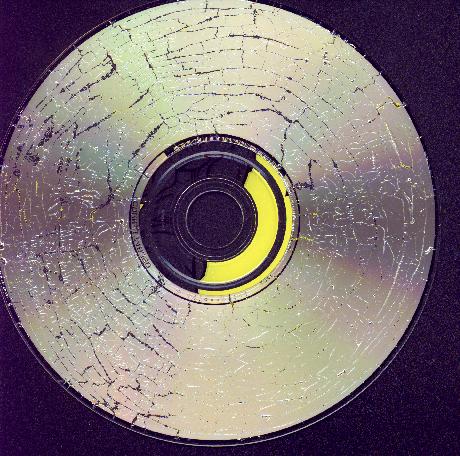
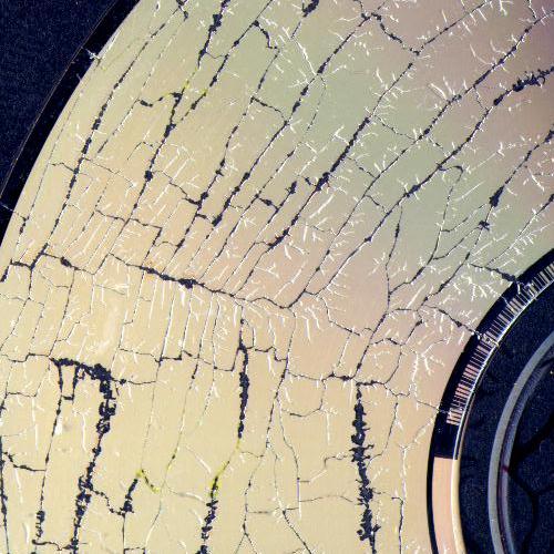
FIG. 4. Branching pattern in target disks. Fig. (a) demonstrates the global pattern, Fig. (b) is close-up of the left side of (a). Note, for scale the disk is 12cm in diameter.
|
|
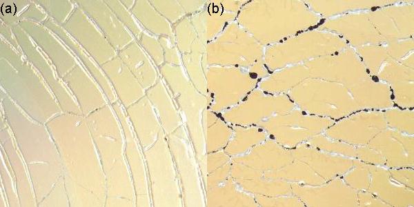
FIG. 5. Examples of (a) azimuthal branching network and (b) random branching pattern.
|
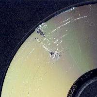
The branching patterns of the CD-R disks were somewhat different than the CD-ROM disks. The branching network of these disks had both a strong annular and radial component, along with a weaker random nature in the finer branches (see Figure 6).
| (a) | 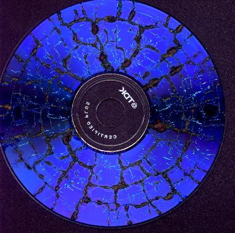
| (b) | 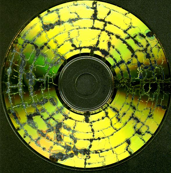
|
|
FIG. 6. Examples of CD-R disks.
|
A number of possible factors had little observable effect on the density or pattern of
the branching network.
These included the position of the disk in the microwave cavity,
the orientation of the disk (label up/down), the disk label pattern
(note reference 6), the disk content
(see Table I), and irradiation interval.
To illustrate just one of these cases, Table II lists the density of the branching pattern as a
function of the irradiation interval. For times less than 3 seconds, no pattern is formed.
For times greater than or equal to 3 seconds the pattern density is almost constant.
The explanation of this effect in relation to the light curve in Fig. 3 will be addressed in the discussion (Section IV).
| time (sec) | fracture density |
| 1 | none |
| 2 | none |
| 3 | high |
| 4 | high |
| 5 | high |
| 6 | high |
The reflective metal layer inside the target disk by default has a high degree of radial and azimuthal symmetry. The irradiation event acts as a phase transition that breaks these symmetries. Therefore, it is interesting to see what effect pre-introduced defects in the metallized film will have on the phase transition. We have investigated three such defects: (1) the data/no data radial boundary, (2) metal scattering centers placed onto the disk, (3) patterns etched into the disk.
Data is stored on a CD starting from small radial distances moving outwards. If the disk is filled to less than capacity, the data/no-data boundary is clearly visible (especially on CD-R disks). For the two CD-R disks shown in Fig. 6 we have measured the fraction of the boundary which has an azimuthal branch associated with it. As a control, we have measured the fractional coverage at arbitrary radial distances. The results are shown in Table III. There appears to be little evidence on any effect of the boundary on the branching network.
TABLE III. Effect of Data/No-Data boundary on the branching pattern. The control case is the average of the fractional coverage at two randomly selected non-boundary radii.
| disk | fraction with branch |
| disk-(a) | 0.145 |
| disk-(b) | 0.25 |
| control | 0.28 ± 0.07 |
One means of introducing non-symmetric scattering centers into the system is to place microwave absorbing materials on the target disk prior to irradiation. Figure 7 illustrates the effect of positioning a small metal target onto the disk surface. The target consisted of a metal wire formed into an open continuous curve, consisting of three 180° bends[7]. This target did have an effect on both the local branching network and 'hot spot' formation. In the vicinity of the target the branching network consists of a number of randomly directed branches emanating from the target, wheareas the global network pattern is predominantly azimuthal.
|
FIG. 7. Induced arc by twisted metal target placed on disk.
|
Another way of introducing defects into the target is to etch patterns into the metal film. Figure 8 illustrates the effects of microwave irradiation of a pre-patterned CD-ROM. As can be seen in the figure, the branching network does not extend into many of the smaller patterns. The branching network that are inside of the preformed patterns are generally of a much finer quality- with narrower branches.

|
FIG. 8. Changes in a pre-patterned CD-ROM.
|
In Fig. 9 we plot how the size of the pre-patterned features (circles, squares, triangles) effect the probability that the feature will be filled in by a branching network. There is clearly a lower limit (~1.5cm) below which branching patterns do not form inside of the patterns. This will be discussed in greater detail in the following section.

|
FIG. 9. Plot of the fraction patterns filled by a branching network versus pattern dimension. Three shapes: circles, squares and triangles are included.
|
As described in Section II.B, the target annulus consists of a thin aluminum or gold layer surrounded by transparent compression molded plastic. When subjected to microwaves inside the cavity, large currents are induced on the central conducting layer. The resulting heating vaporizes the metal at different locations on the target. Discharges are subsequently observed across the vaporized areas, and over the surface of the target. Inspection of the disks after the microwave pumping has ceased reveals a large amount of ablation of the painted surface where the discharges occurred. The combination of discharges and ablative heating of conductive material etch long, fractal-shaped channels within the metal.
Once a flashover discharge occurs the metal film is essentially divided into a number of smaller cells divided by the etched channels. If any one of these cells is larger than the critical cell size of about 1.5cm, another discharge arc can occur. In the absence of any cells of sufficient size, all of the microwave radiation absorbed by the disk is concentrated in the isolated 'hot-spots'. These glowing hot-spots are small discharges of ionized gas that are good absorbers of microwave energy. As a test of this idea, we have measured the largest branch-free zone in standard (non-etched) targets as a function of irradiation time. The largest branch-free cell size was 4cm by 1cm in disks processed for 3 seconds, 2cm by 1cm in disks processed for 4 seconds, and 1.5cm by 0.8cm in disks process for 5 or more seconds. Presumably if we had irradiated the three second disk longer, an additional flashover event would have occurred in the open cell.
The initial arcing occurs about three seconds after turning on the magnetron, but the subsequent flashovers occur at only ~0.2s intervals. There are two possible explanations for this initial long delay. One possibility is that it takes some time for the disk to sufficiently heat up to the point where a discharge will occur. Once that point is reached, the first flashover discharge occurs. The plasma generated by this arcing absorbs the microwaves in the cavity temporarily preventing further heating of the disk, however the disk has little time cool significantly. So once the absorbing plasma dissipates there is only a short delay until subsequent discharges.
A more likely reason for the long initial delay lies in the magnetron itself. A magnetron consists of an electron beam circulating inside a resonant cavity [8.9]. The electrons come from heating a filament to the point where electrons are 'boiled' off, while the beam is prevented from crashing into the sides of the resonant cavity by a combination of electric and magnetic fields. When the magnetron is first turned on it takes some time to warm up the filament inside the magnetron and power-up the high voltage supply used to generate the proper electric field. Thus, the long initial delay is not due to some required heating of the target disk, but represents the delay between turning on the magnetron and the magnetron generating large amounts of microwave power.
We supply two lines of reasoning for this second effect as being the primary explanation for the long initial delay. First, commercially available microwave ovens often used in this work come in a wide variety of maximum power levels[10]. Yet the optimum time required to process a disk is fairly similar for different investigators[1-4]. If the power is going into the initial heating of the disk, then investigators with lower power sources should find it take longer for a discharge to occur than investigators with high powered sources. More convincingly, we can test this proposition ourselves by running our apparatus at a reduced low-power setting. At the 10% power level, one would expect about a 25 second delay before the first discharge occurs if the intial delay is due to heating of the disk. We observed, however, only about a three second delay consistent with our second hypothesis.
During these experiments it was observed that after four to five seconds of exposure to microwave radiation, discharges across the face of the target disk ceased, and various points across the target were observed to glow red-hot. We account for termination of the observed arcing by the absence of metal film patches of sufficient size to act as good absorbers of microwave energy.
The authors wish to thank AOL, Compuserve, the Thomas Register, WEBTechniques, Keithely, National Instruments, Goodfellows and Microsoft for providing target samples.
- T. Atwell,"CD Burning by Microwave"
- "CD-ROM's in the Microwave"
- R. J. Spiess Jr., "CDnuke"
- B. Beaty, "Unwise Microwave Oven Experiments"
- Sharp Microwave Owner's Manual. A comercially available model R-3A74 Carousel II microwave oven was used for most of this work.
- Although it is hard to draw conclusions from one event, there may be some relation between the branching network and label pattern. Our one case of an asymmetric branching pattern occurred in a disk with a label that was half white, half black. On the black side, where the branching network was more extensive, the label was measured to be 1 um (0.0005") thicker than the white side. On the other hand, this disk was irradiated for only 3 seconds, which may not have been enough time for a full flashover discharge to propagate through the disk. None of our other samples had a similar asymmetric label, and another disk irradiated for only 3 seconds did have a fully developed network.
- We have found wires bent into this shape useful for temporarily binding papers together. A subsequent publication on this "paper clip device" is forthcoming.
- L. A. Bloomfield, How Things Work: Microwave Ovens
- Alistair Steyn-Ross and Alister Riddell, The Physics Teacher 28 (1990) 474.
- "Appliance Superstore Advertising Supplements", Wisconsin State Journal, August 22,1999.